Artifacts in Complex Development Projects
Summary of Most Relevant Topic Papers
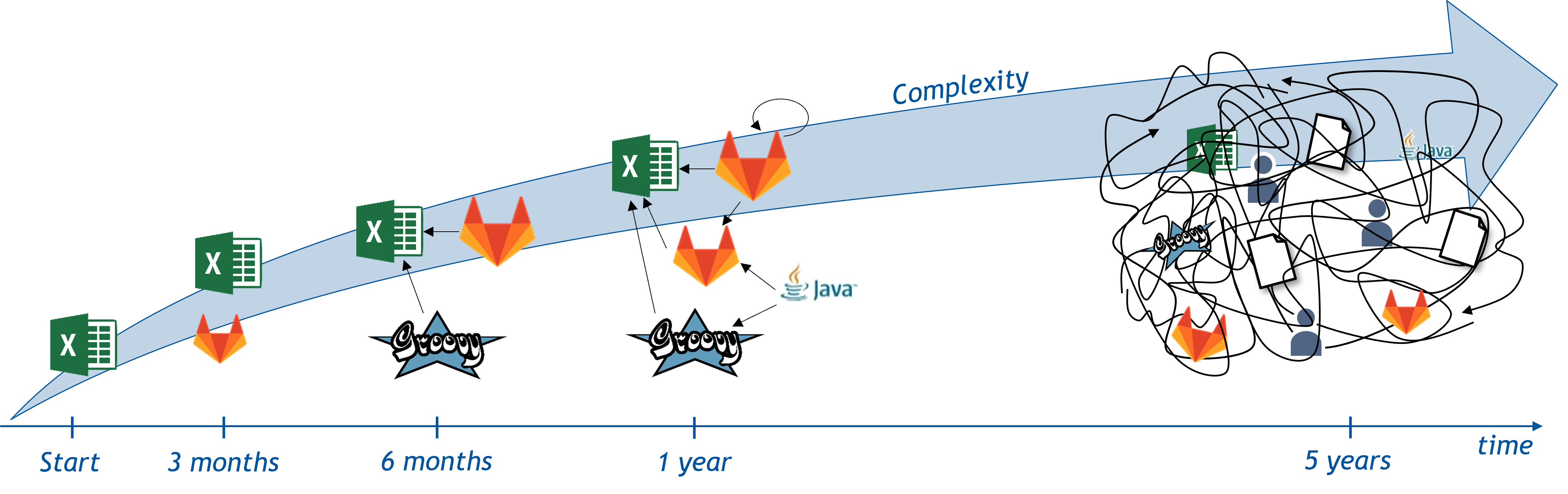
Most development projects over time evolve from a simple, understandable collection of artifacts, tools, and the way they relate to each other into a complex, incomprehensible compound of artifacts, tools, and developers who work with them. The following figure illustrates this evolution with a simple set of tools and the artifacts they produce and edit. The arrows between the tools and artifacts represent the relations.
Especially, developing modern software solutions has become an increasingly complex and time consuming process. As both the requirements and expectations towards modern software increase, the need for the development of increasingly large and complex systems arises. In general, the larger the developed system needs to be the more developers will be involved in the creation process in order to finish the project in an acceptable timespan [BGRW17]. Often problems arise when large groups of people have to cooperate on the same project over a longer period of time. For example, architectural decisions made years ago, might be difficult to understand once the responsible architect moved on to the next project. But even if the original contributors of the project are present the complexity of large software systems often becomes overwhelming to a point where people can easily lose track of relevant structures, artifacts, and their relations.
A good example is Model-driven development (MDD). As a prominent enabler for the automatic generation of programming language files for products or for tests from explicitly defined models, MDD projects manage a large magnitude of artifacts (files, etc.) with various relationships. A large class of artifact relations comes from artifacts using others, e.g., via importing types and signatures. This form of usage strongly differs from generation dependencies, where one artifact is generated, compiled, and transformed from or to other artifacts [BGRW18]. An MDD project usually entails a number of potentially dependent process steps, where a chain of generating, compiling and packaging artifacts arises. During these steps a multitude of artifacts are created, read or even executed. Those artifacts are thus related to each other in various ways. The number and complexity of occurring dependencies and other relationships between development artifacts can lead to several problems, such as poor maintainability and long development times of both, MDD tools and the product, in an MDD process. To tackle these problems, it is important to understand which artifacts are involved and how these artifacts are related to each other in MDD projects.
Leaving the domain of software development and entering the domain of cyber physical systems (CPS) engineering the problem of complex project structures becomes even more pressing [BHR+18]. Here, development projects have a much wider range. Now, not only the relations of processes, structures, and artifacts of one single domain, for instance mechanical engineering, need to be understood but their relations within and between several domains. At the core is the problem of undocumented knowledge of project, process, and artifact structures. Somehow somebody knows what to do at a certain point in time of a project. It is known that artifacts of a certain type always can be found at a specific place (on a file system, database, etc.). It is also known that once artifacts of this type are modified, other artifacts, processes or departments might be affected by the change. A first step of dealing with this problem is making the implicit knowledge explicit. This step, however, needs a precisely defined methodology which provides modeling languages and techniques.
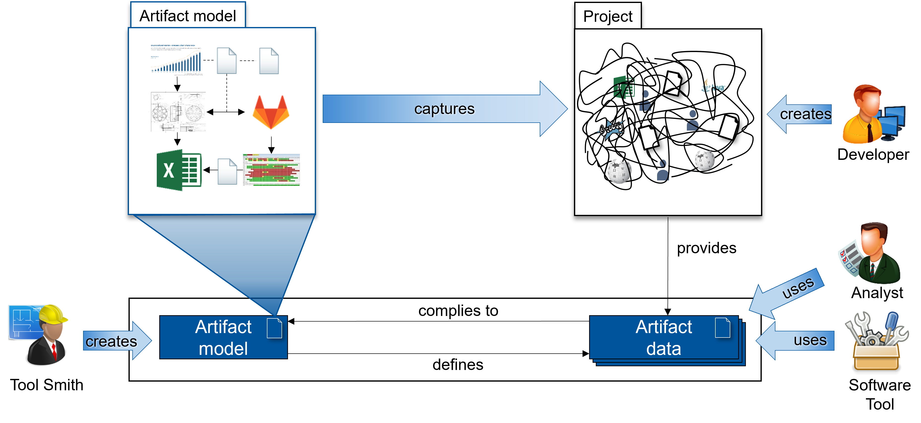
The previous figure shows how to handle the complexity of model-driven systems engineering projects with artifact models. Furthermore, it shows the relations between the involved stakeholders and the artifact model, as well as, the artifact data. An architect creates the artifact model for a systems engineering project shown on the left side of the figure. Its goal is to structure all the different kinds of artifacts and their relations within the project created by people involved in it, represented by the developer icon shown on the right side of the figure. Corresponding to the artifact model, artifact data is extracted from the project. This data contains information about all artifacts and their relations of the project in its current state. Analysts, shown on the right side of the figure, use this data to check the current state of a project. Additionally, the artifact data can be used as input for software tools for further processing.
Modeling artifacts and their relations
At this chair we developed a methodology providing modeling techniques and corresponding tooling which help to understand artifacts in complex development structures [GHR17]. We provide a way to define a custom artifact model for a project, department or a company which describes artifacts and their relations. Additionally, we provide a customizable tool-chain which extracts artifact information and performs analyses on this artifact data. This data then can be further used by analysts or software tools to help understand, analyze, and improve complex development projects [Gre19].
Understanding architectures, substructures & erosion
One example for an analysis based on the artifacts and their relations is understanding architectures and substructures of development projects, as well as, analyzing the architectural erosion occurring over time. We used our modeling techniques to create tooling which analyzes and calculates the architectural drift based on the project’s artifacts and their relation. Once an architect defines the concept architecture of a project, the current architecture can be automatically check with respect to the concept.
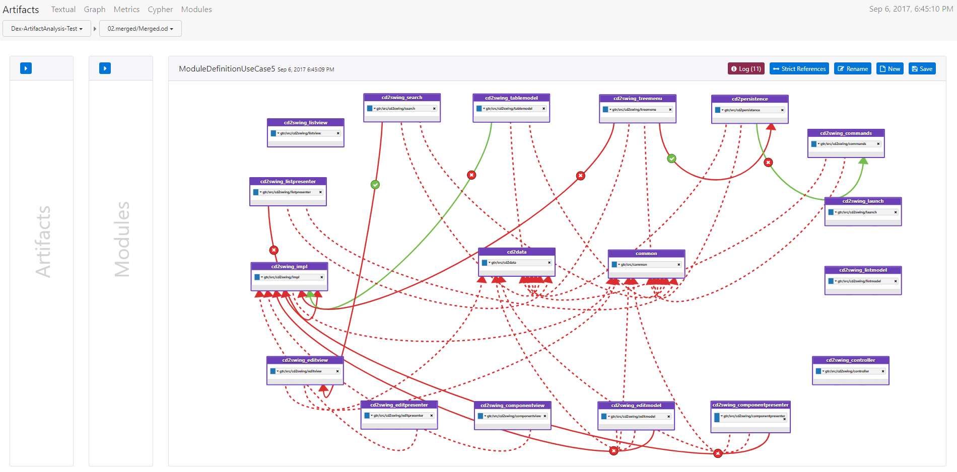
The last figure illustrates the results of such a calculation of the architectural drift. After creating the artifact model for the project, a tool-chain automatically extracts the artifact data of the project in its current state. Additionally, an architect defines which modules exists in the project and which relations between them exists (illustrated by the boxes and arrows). A module in this case is a conceptual container for artifacts which does not need to correspond to any file structure within the project. The architect also adds information to the relations between the modules by declaring which relations must exists and which are not allowed illustrated by the arrows’ coloring and icons. Hence, he defines the concept architecture of the project. This architecture is then used to calculate the architectural drift of the the current architecture, meaning the current relations between the modules, reconstructed from the artifact data of the project. The icons on the arrows indicate which relations between modules must exist (green check) and which are forbidden (red cross). The arrows represent relations between modules. The coloring of the arrows illustrates if the constraints defined by the icons whether a constraint is stratified. As an example, a red arrow with a red cross from module A to module B means that any relations between artifacts contained in module A to artifacts in module B are forbidden, however, in the current architecture this is not the case. Moreover, dashed arrows indicate relations between modules which are not modeled by the architect.
Understanding project structures & tooling
Moving away from the artifact layer, we applied our methodology for modeling artifacts and their relations within complex projects to tools and their relation. In a first prototype we analyzed the structure and relations of repositories, CI/CD, and documentation tooling in an overlapping fashion. This way, we were able to understand artifacts and their relation within the tools, but also across them, giving us the opportunity to create an overview of our project and further analyze it.
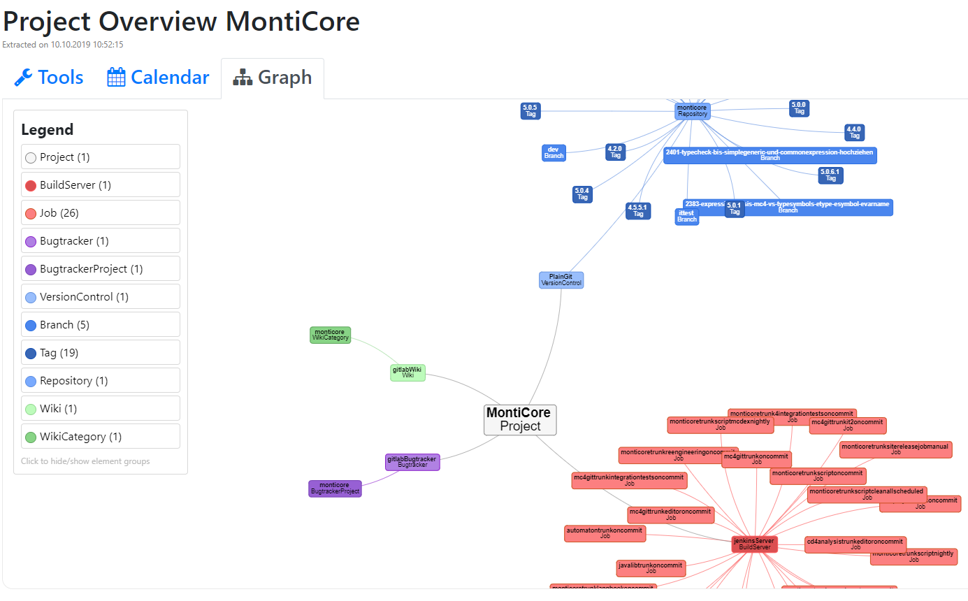
The figure demonstrates our attempt to leave the layer of a file system to perform artifact-based analyses and move to the layer of tools and their relations within a project. Based on an artifact model created to understand artifacts which are primarily located on the level of a file system, we added the information of different tools and their relations to the model. In the figure these are the wiki (green), bugtacker (purple), jenkins build server (red), and git repositories (blue). The figure shows an overview of all these tools which are part of our own MontiCore project. By using the concept of artifact-based analyses, we are able to better understand not only the artifacts and their relations within a project, but also the type of tools which are involved and the artifacts they work with.
Key Statements
- Modeling artifacts and their relations tackles two problems of complex development systems:
- Making implicit knowledge about process, structures, and artifacts explicit, as well as,
- enabling analyses of the artifact data to understand and improve projects.
- This is even more beneficial once the domain of CPS development is entered and projects span across multiple departments and a multitude of tools [HJK+21].
- We have developed a methodology providing modeling techniques to help understand artifacts and their relations in complex development projects. Furthermore, we created a customizable tool-chain which enables automated extraction and analyses of artifact data of model-driven systems engineering projects.
Selected Topic-Specific Publications
-
[HJK+21]In: Model-Based Engineering of Collaborative Embedded Systems, pp. 315-331, Springer, Jan. 2021.
-
[Gre19]Aachener Informatik-Berichte, Software Engineering, Band 42, ISBN 978-3-8440-6879-5, Shaker Verlag, Aug. 2019.
-
[BHR+18]In: Joint Proceedings of the Workshops at Modellierung 2018 (MOD-WS 2018), Volume 2060, pp. 67-77, CEUR Workshop Proceedings, CEUR-WS.org, Feb. 2018.
-
[BGRW18]In: Software Technologies: Applications and Foundations, M. Seidl, S. Zschaler (Eds.), pp. 146-153, LNCS 10748, Springer, Jan. 2018.
-
[GHR17]Aachener Informatik-Berichte, Software Engineering, Band 30, ISBN 978-3-8440-5678-5, Shaker Verlag, Dec. 2017.
-
[BGRW17]In: Part of the Grand Challenges in Modeling (GRAND’17) Workshop, Jul. 2017.
Related Topics
- Automotive
- Autonomous Driving & Intelligent Driver Assistance
- Domain Specific Languages (DSLs)
- Energy Management
- MontiArc - Architectural Modeling
- Robotics Architectures and Tasks
- Unified Modeling Language (UML)